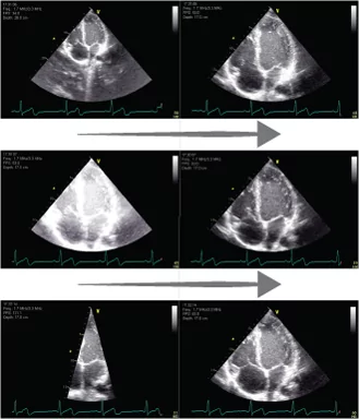
The ultrasound image can be optimised by adjusting different user controls
The most important user controls are:
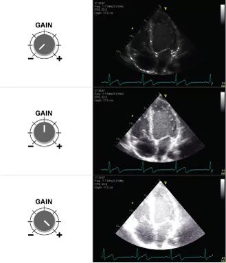
– Gain
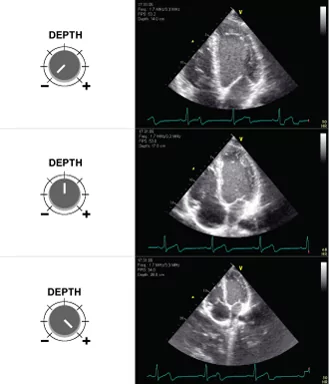
– Depth
– Sector angle
– Time Gain Compensation
These user controls will be explained in greater detail in the next slides
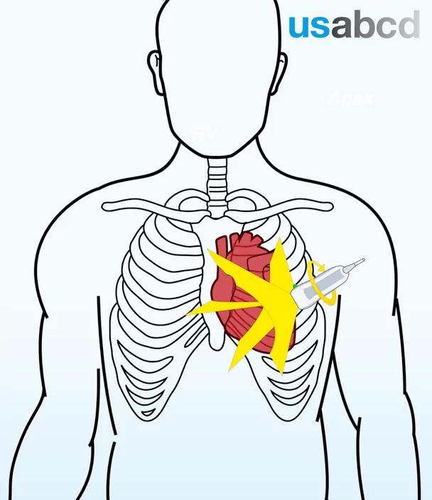
It is important that you become familiar with these user controls on your own ultrasound system so you know how to optimise the ultrasound image in order to improve the diagnostic value of the images