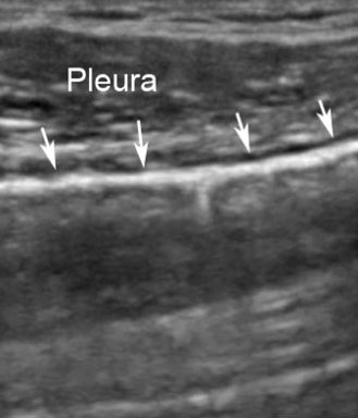
Ultrasound cannot penetrate the airfilled lung parenchyma, because of the large difference in acoustic impedance between soft tissues and air.
The apparent lung parenchyma looks hypoechoic (greyish) but it is a reverberation artefact (see the next module about artefacts).
The picture shows the white arrows pointing at the hyperechoic pleura, which is a specular reflector. Ultrasound cannot penetrate air and the underlying greyish apparent lung parenchyma is a reverberation artefact.
Usually M-mode is displayed together with a 2D greyscale ultrasound image to allow spatial reference.
The 2D image has a graphical M-line superimposed to indicate the position of the M-mode beam that samples the data.
Lung ultrasound with M-mode displayed together with a 2D greyscale ultrasound image. The M-line is superimposed on the 2D image to indicate the position of the M-mode beam.
Colour Doppler displays a real-time 2D cross-section of blood flow.
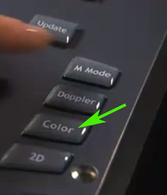
When the colour Doppler is activated, the cross-section is displayed as a frame on the monitor. The shape of the frame depends on the probe. The position of the frame can be moved around using a touch pad.
Spatial orientation is obtained by overlaying the colour Doppler cross-section on top of a 2D greyscale ultrasound image displaying the soft tissues.
Conventionally, red colour is used for blood moving towards the probe, and blue is used for blood moving away from the probe.
The red arrow points at the activated Color Doppler frame. The Green arrow points at the touch pad used to adjust the position of the Color Doppler frame on the monitor.
Colour Power Doppler (CPD) like standard colour Doppler detects blood flow through arteries and veins.
CPD does not indicate the velocity or direction of blood flow.
CPD is based on the echo amplitude received from moving cells – not the frequency shifts.
CPD is up to five times more sensitive than colour Doppler in order to detect the velocity of blood flow and can detect low velocity blood flow in veins and within organs. The strong flow sensitivity is the real benefit of CPD.
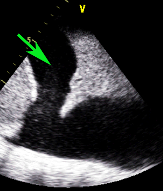
The goal of depth adjustment is to align the target structure to the center of the monitor and to visualise the entire target structure inside the visual field.
This illustration shows an ultrasound image of the heart with different depth settings. The top image is too shallow, the depth of the middle image is appropriate, and the depth of the bottom image is too large.
The size of the displayed image can be adjusted using the depth controls.
When the depth of the field-of-view (FOV) is increased, it becomes possible to see deeper structures.
When the depth is decreased, the FOV is narrowed around structures closer to the probe, thereby omitting the deeper structures.
Reduction of the depth means that the time from emitted to received signal is reduced. This allows a higher frame rate. Higher frame rate can be used to increase the spatial or temporal resolution or the sector width.
Different depth settings depending on the position of the target vessel.