A ring-down artefact occurs when the transmitted ultrasound energy causes resonant vibrations within fluid trapped between air bubbles.
These vibrations create a continuous sound wave that is transmitted back to the transducer.
This phenomenon is displayed as a line or series of parallel bands extending posterior to a gas collection.
Air and fluid in the duodenum often cause ring-down artefacts.
If the US beam hits a pocket of vibrating fluid surrounded by air bubbles, then the vibrating fluid generates a narrow, continuous transmission of sound that the US system displays as an echoic line on the monitor (see next slide).
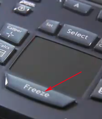
You are now familiar with the ultrasound system, the probe and how to optimize the ultrasound image:
? Preparation of the ultrasound (US) system ? Selection of the appropriate ultrasound probe ? Appropriate placement of the US system, the patient and yourself ? Probe orientation, grip and movement ? Anatomy planes ? Acoustic coupling with ultrasound gel ? How the ultrasound beam is equivalent to a tissue slice ? How to optimise the image quality (depth, gain and focus) ? Imaging modes (B-mode, M-Mode, Colour Doppler and Power Doppler) ? Freeze, save, measure ? Image recognition
When performing ultrasonography, image artefacts are commonly encountered and may be confusing for the physician. Some artefacts can be avoided using correct scanning technique. Other artefacts are generated by the physical limitations of the modality.
Ultrasound artefacts arise secondary to errors inherent to the ultrasound beam characteristics, the presence of multiple echo paths, velocity errors, and attenuation errors.
Shadowing, refraction, reverberation, comet tail, ring-down and mirror image are some routinely encountered artefacts in clinical ultrasonography practice.
The learning objective of this module is to recognize, interpret and remedy potentially correctable US artefacts because it is important for image quality improvement and optimal patient care.
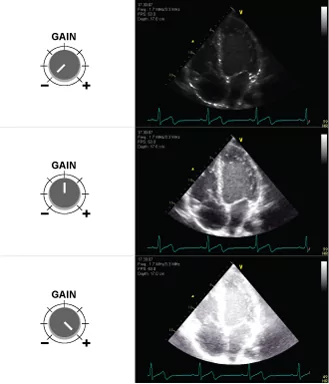
Many acoustic artefacts seen during an ultrasound examination can be directly attributed to the incorrect use of the ultrasonic hardware.
The most common mistakes are overgain and undergain artefacts.
Too low gain settings may result in the apparent absence of an existing structure (i.e. “missing structure” artefact), whereas too high gain settings can easily obscure existing structures.
Undergain: If the gain control is too low, the amplification of the electrical signals becomes too small and the 2D greyscale image on the screen becomes too dark.
Overgain: If the gain control is too high, the result is overamplified electrical signals including artefactual noise and the 2D greyscale image becomes too bright (white).
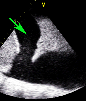
The illustration shows an ultrasound image of the heart with different gain settings. The top image is undergained, the middle has optimizsd gain, and the bottom image is overgained.
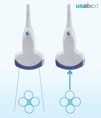
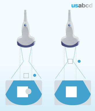
Inappropriate focus points may result in beam width artefacts where echoes generated by the object located in the peripheral field are displayed as overlapping the object of interest.
The importance of adjusting the focal zone to the depth of the target structure is shown in the illustration.
The lefthand figure shows a structure within the field of the US beam (blue lines) but outside the area that the US system assumes to be the visual field (within the two dotted lines). The structure overlaps the target structure (the white rectangle). The righthand figure shows the effect of aligning the focal zone and the round structure.
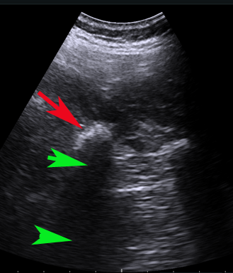
When the ultrasound pulse meets a border between two different tissues with a large difference in acoustic impedance, the pulse is almost entirely reflected by the tissue border.
That is why the surface of bone looks hyperechoic (white) with an anechoic (black) acoustic shadow extending from the bony surface to the bottom of the image on the screen.
Image of the transverse process of lumbar vertebrae L5 in cross section with a curved array transducer. The red arrow points at the hyperechoic bony surface of the transverse proces. The green arrows point at the anechoic (black) acoustic shadow extending from the transducer-near surface of the transverse process to the bottom of the image.
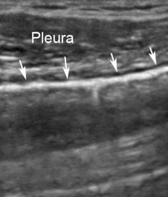
Ultrasound cannot penetrate the airfilled lung parenchyma, because of the large difference in acoustic impedance between soft tissues and air.
The apparent lung parenchyma looks hypoechoic (greyish) but it is a reverberation artefact (see the next module about artefacts).
The picture shows the white arrows pointing at the hyperechoic pleura, which is a specular reflector. Ultrasound cannot penetrate air and the underlying greyish apparent lung parenchyma is a reverberation artefact.
That allows the operator to perform measurements on the frozen image, or save the image, or scroll through the images sampled e.g. 15 seconds before freezing the image.