A ring-down artefact is displayed as a line or series of parallel bands extending posterior to a gas collection.

A ring-down artefact is displayed as a line or series of parallel bands extending posterior to a gas collection.
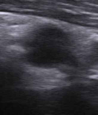
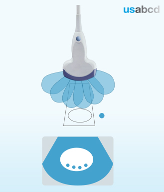
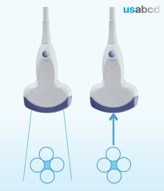
A side lobe artefact occurs when the probe cannot produce a pulse that travels exclusively in one direction. Pulses can also travel off at specific angles.
Side lobe artefacts are relatively weak and therefore normally do not degrade the image.
Their effect is usually just weak superimpositions in fluid filled areas, such as the gallbladder, which are anechoic and do not obscure the weak side lobe reflections.

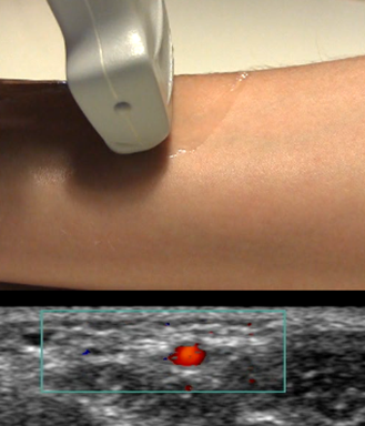
Doppler is an important technology in screening for blood flow in vessels or the movement of an anatomical structure.
The major concern for the physician is to make the false negative conclusion that a blood vessel is not a blood vessel when no flow is seen. Doppler technology allows the assessment of both velocity and directionality of blood flow. Accurate assessment of blood flow requires that the direction of the flow is parallel to the ultrasound beam. This is due to the Doppler equation.
In most cases, US imaging of blood vessels is performed along the short axis, and, therefore, the blood flow is perpendicular to the ultrasound beam. As the angle of the blood flow approaches 90 degrees, the cosine of this angle approaches zero thereby creating an artefactual non-detection of flow.
Two types of Doppler imaging modes are frequently set up on ultrasonic scanners, namely colour Doppler imaging (CDI) that allows estimation of the velocity of the blood flow and Power Doppler that provides more sensitive detection of low-flow compared to CDI.
You have now learned to recognise, interpret and remedy some of the common and potentially correctable ultrasound artefacts:
– Shadowing artefact
– Refraction artefact
– Reverberation artefact
– Ring-down artefact
– Mirror image artefact
– Side lobe artefact
You have now learned about the basic concepts of waves, sound waves, ultrasound, the ultrasound system, system and user controlled ultrasound imaging, ultrasound imaging artefacts, and patient safety.
You have gained knowledge of the basic principles of:
? wave physics and acoustic physics
? ultrasound and medical ultrasound
? the ultrasound system
? the system controlled ultrasound imaging
? the user controlled ultrasound imaging
? the ultrasound imaging artefacts
? patient safety
Reverberations occur as the result of ultrasound waves bouncing back and forth between two strong specular reflectors. The result is usually multiple linear and hyperechoic areas emanating distal to the reflecting structures.
A linear artefact is generated when tissue with a linear surface participates in a reverberation process, which reproduces the image of the linear surface at a distance from the transducer which is twice the distance from the transducer to the actual location of the linear surface.
A strong specular reflector such as the pleura produces hyperechoic linear artefacts, known as A-lines, which can be seen “mirrored” in the underlying US image.
Multiple reverberations can be generated by the US waves reverberating in lung tissue with increased density producing a hyperechoic vertical reverberation artefact known as a B-line.
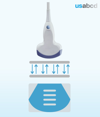
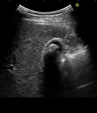
A ring-down artefact occurs when the transmitted ultrasound energy causes resonant vibrations within fluid trapped between air bubbles.
These vibrations create a continuous sound wave that is transmitted back to the transducer.
This phenomenon is displayed as a line or series of parallel bands extending posterior to a gas collection.
Air and fluid in the duodenum often cause ring-down artefacts.
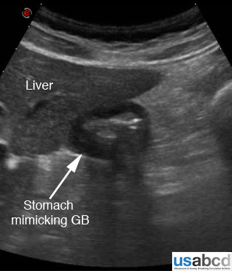
Anatomic artefacts are often referred to as “pitfall errors”.
The simplest solution to avoid pitfall errors is to trace the scanned anatomical structure along its expected anatomical course.
Some closely related structures may mimic the examined structure e.g. a sagittal view of an empty contracted duodenum may mimic a gallbladder.
This can generally be avoided by examining an anatomical structure in multiple planes.
Acoustic shadowing occurs when a structure has a larger attenuation coefficient than the tissue that lies deeper to it, causing the deeper tissue to appear far less echogenic than normal.
The echoes returning from structures beyond the highly attenuating structure will also be diminished.
In clinical imaging, this phenomenon is recognized as a dark or hypoechoic vertical band mimicking a “shadow”.
A classic example of acoustic shadowing is that seen below a stone in the gallbladder.
Enhancement is the situation where the ultrasound beam encounters a structure within the imaging field with focal weak attenuation, and the amplitude of the beam beyond this structure is higher.
The echoes returning from structures deep to the focal weak attenuator will be of higher amplitude and will be falsely displayed with increased echogenicity.
For example liver parenchyma below a simple cyst will appear more hyperechogenic when compared to a neighbouring liver parenchyma not placed below the cyst.