Cardiac ultrasound

Sector angle


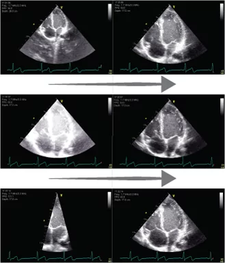
The sector angle is important as it affects the frame rate dramatically

A narrow sector angle (width) allows either (1) a higher frame rate (the time required to build the image is reduced by reducing the number of beams for a whole sector) or (2) a better lateral resolution (the line density can be increased).

A higher frame rate increases temporal resolution

A higher line density increases lateral resolution

By using a sector just wide enough to include all relevant details, the capacity of the ultrasound system capacity is best used

Image missing
Different sector angles for an apical 4 chamber view of the heart. The middle image has an appropriate sector, where all relevant parts of the heart can be seen. In the top image the sector angle is too narrow, and in the bottom image the sector angle is too broad.

Time gain compensation (TGC)


TGC is a user controlled selective amplification of signals reflected from particular depths in the tissue

TGC compensates for the depth-dependent attenuation of the ultrasound wave

A typical user control panel is illustrated in the image

Image missing
By fine tuning TGC, optimal image quality can be achieved at all depths of the image.
In the top image TGC is increased in the upper bands resulting in increased (more white) gain in the near field. In the bottom image TGC is increased in the lower bands. The middle image has appropriate TGC.

Summary – Equipment and skills


You are now familiar with the ultrasound system and the probe and how to optimise the ultrasound image

After testing your new knowledge with a few quiz questions, you are ready to start the lessons about the FATE protocol

The questions will prepare you for the final quiz at the end of the course

Click on the quiz in the side menu to start it

Image missing

Full Basic FATE examination

A full Basic FATE examination includes images of the heart and pleura obtained from four different positions, or “windows”, in the thorax

From these positions 6 imaging views can be achieved:
– Position 1: Subcostal 4-chamber view
– Position 2: Apical 4-chamber view
– Position 3: Parasternal views: the long-axis and short-axis view
– Position 4: Pleural views. Right pleura and left pleura

This module will give an overview of these 6 imaging views and how to achieve them

At the end of module 4 (position 1) inferior vena cava (IVC) has been added as a service for those of you who want to learn IVC now

IVC is one of the extended views and therefore a part of Advanced FATE

Image missing
This image shows the FATE positions on the FATE torso and corresponding cardiac positions on a human body

Display of the sector on the screen


The ultrasound image on the screen can be turned upside/down or left/right with user controls

In FATE and adult cardiac ultrasound, the ultrasound image displays the sector with the two radii diverging from the top of the screen

The OI is on the right side of the screen, and the arc of the sector is displayed towards the bottom of the screen

Image missing
The video clip shows the ultrasound sector placed correctly and incorrectly. Remember that the right orientation is with the top of the sector pointing upwards, and the orientation indicator (OI) on the right side of the screen.

ECG


Connect ECG to the patient in order to generate and save echocardiographic loops

Image missing

Image optimisation


The ultrasound image can be optimised by adjusting different user controls

The most important user controls are:
– Gain
– Depth
– Sector angle
– Time Gain Compensation

These user controls will be explained in greater detail in the next slides

It is important that you become familiar with these user controls on your own ultrasound system so you know how to optimise the ultrasound image in order to improve the diagnostic value of the images

Image missing

Gain: Undergain & overgain


This user control is similar to the brightness control of a television set

Some of the emitted echo signal is reflected back to the probe when the emitted beam hits a reflective interface in the tissue

The echo signal returning from the tissue is converted to an electronic signal by the probe

This signal is very weak and has to be amplified before it is processed into a greyscale image. The signal amplification is called “gain”

Undergain: If the user sets the gain control too low, the amplification of the electrical signals is too small, and the 2D greyscale image on the screen becomes too dark.

Overgain: If the gain control is set too high, the 2D greyscale image becomes too bright

Image missing
The image shows an ultrasound image of the heart with different gain settings

The top image is undergained, the middle image has optimised gain, and the bottom image is overgained

Depth: Keep all relevant details in the image


The depth of the displayed image can be adjusted using the depth controls

When the depth of the field-of-view (FOV) is increased, it becomes possible to display deeper structures

When the depth is decreased, the FOV is narrowed around structures closer to the probe and deeper structures are omitted

Reduction of the depth means that the time from emitted to received signal is reduced; this allows a higher frame rate

Image missing
Ultrasound image of the heart with different depth settings. The top image is too shallow, the depth of the middle image is appropriate, and the depth in the bottom image is too great.

Rotation


During a “clean” rotation, the direction of the tail of the transducer should be kept 100% stable

Rotation can be:
– Right = clockwise
– Left = counterclockwise

For rotational instructions we do not make use of a secondary reference point

Example:
To obtain the correct subcostal 4 chamber view, alignment with the longitudinal axis of the heart often requires 10-20 degrees counterclockwise rotation

You will therefore often hear the supervisor saying: “Rotate the probe counterclockwise or rotate the transducer to the left”

Image missing
Rotation as it takes place in the parasternal view